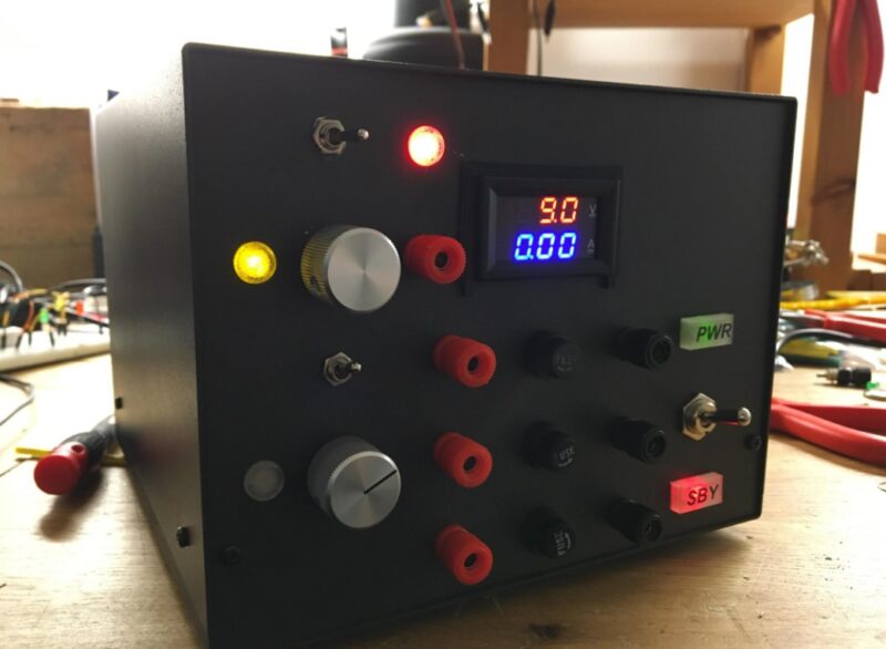
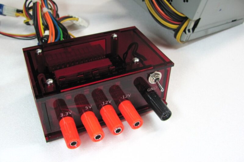
This tutorial will show you how to convert an ATX power supply into a bench supply.
The convert atx power supply to variable benchtop pdf is a document that describes how to convert an ordinary ATX power supply into a benchtop variable power supply.
The procedures to convert a 20-pin Molex ATX connector to a Bench Supply will be discussed. The following are some of them:-
Step 1:
Keep the 20-pin Molex connection intact or cut it off entirely and arrange the different wires together, keeping the same colors together (yellow to yellow, blacks to blacks, and so on).
Step 2:
Now you must connect pin 14 – Green (Power-ON) to one of the common black wires (ground) to instruct the motherboard to switch on the power supply.
When pin 14 is connected to ground for a period of time or permanently via a switch, the power supply will turn on.
Step 3 :
To fool the PSU, you must now provide a modest load to the +5V (red wires) output.
This technique fools the PSU into thinking it’s connected to the motherboard, causing it to stay in “ON” mode.
What is the best way to accomplish this?
With only one pair of red and black wires, connect a resistor of 10 Ohms or fewer across the +5V output, with a typical power rating of 5W to 10W. (pins 3 and 4 ).
If you know the Ohms Law, you can connect this to the equation:-
P = I2 R or P = V2 / R are two different ways of expressing the same thing.
Where
- P = watts of power produced in the resistor (W),
- I = amps of current flowing through the resistor (A),
- R is the resistor’s resistance in ohms (ohm)
- In volts, V is the voltage across the resistor (V)
The voltage will be +5V, and the necessary power will be 5W or more, resulting in a very hot device.

Step four:
When you’re finished, you’ll have something like this:-
After connecting the PSU into the wall socket, you must flip the switch “ON” since there are only two voltages present at the connection on the back of the power supply. The following are some of them:-
- pin 14
- pin 9
The power control buttons on the motherboard are controlled by these two voltages.
The following wires should now be connected. They are as follows in the main power cables:-
1.) Connected together are three red wires (+5V).
2.) Three black wires (0V) are connected as follows:
- Three orange wires provide a +3.3V output for powering microcontroller boards or other tiny devices.
Step 5 :
If you’ve followed the steps properly, the PSU should turn “ON with Bench Power Supply.”
Check the voltages at the output.
Step 6 :
You may test the Bench Power Supply with a voltmeter or by plugging a 12V bulb into each socket.
The PSU may provide a variety of voltage combinations as an output, including the following:-
- 24 volts (+12 volts, -12 volts),
- 17 volts (+5, -12 volts),
- 12 volts (+12 volts, 0 volts),
- 10 volts (+5, -5 volts),
- 7v (+12, +5), 7v (+12, +5), 7v (+12, +5)
- 5 volts (+5, 0)
The convert computer power supply to 12v is a question that has been asked before. If you are looking for information on how to convert your ATX PSU into a bench supply, this article will help you out.
Frequently Asked Questions
How do you convert an ATX power supply to a bench supply?
If you have an ATX power supply, then you can use a bench power supply converter.
Can I replace my PSU with any PSU?
Yes, you can replace your PSU with any PSU.
Can you get 24V from ATX power supply?
There is no way to get 24V from an ATX power supply.


